Friday, November 29, 2013

PROCESS DESIGN by Dian Pramesti


The design is the ability to combine ideas , scientific principles , resources and existing products developed for the settlement of the problems associated with the level of customer satisfaction of the product
The ability to solve this problem is the result of an organized approach and is a regular on the settlement of an issue , this is called the design process


Figure chart design process


The design process always leads to the manufacture , assembly , marketing . many services and activities required for a product that we know . Although many of the industries identified in their own ways , but the most straightforward procedure for the design of new products or improvement of the old design , through the following five stages
1 . Identify the problem
2 . Concepts and ideas
3 . Compromise on the settlement issue
4 . Model or prototype
5 . Image production and working drawings

Supposed to be a walk through the five stages of design mentioned above , if one part can not give good results and useful , it is necessary to find the root of the problem by going back to the original stage and repeat the procedure at each stage .

1 . PROBLEM IDENTIFICATION
Design activity begins with the identification of the problem to the needs of consumers for a product that will be created or improved on certain products . In this case the designer must identify the needs of consumers for a product which is a result of the pendisain.Tentukan if the results of the design will be used by whom ? And how to use it .

2 . CONCEPT AND IDEAS
In this stage , all the ideas that make sense and do not make sense together in one section , for further analysis so as to form a concept of design thinking from an expert on how the design is made ? How much it cost ? How much profit will be in the can ?

3 . PROBLEM TO COMPROMISE SETTLEMENT
In this stage , all the ideas and results that have been collected and has been a concept in mind , the design expert seoarang must have compromise from within ourselves to settle the existing problems .

4 . MODEL OR PROTOTYPE
One form of compromise to the problem is to make a model or prototype.baik through the media or through CAD modeling real form , for example from resin ( fiberglass ) . At this stage prototype that has been made ​​, re- studied the shape , the fabric , the strength of the material , if the design is made ​​to move , it is necessary to carefully re , how the movement , driving source , all these things lead to one goal is to convince yourself that design has been made in accordance with the plan .

5 . FIGURE DRAWING AND PRODUCTION WORK
Once a model or prototype is made the next step is to create production drawings and working drawings . Image production is made as material for a presentation on the design , using a wide variety of applications created on CAD ​​systems , working drawings made ​​to obtain further action on the part that is in the process of the production process , so that the design can actually be realized in the form of a product

Monday, November 25, 2013

Development of prototypes


Prototypes were developed, based on AutoCAD and the Swedish AEC application Point. In the resulting applications the structuring of information in layers has been combined with a model-oriented approach to 2D CAD. Documents are produced using file references with a model space/ paper space system. All information is stored on file servers in a company wide network. Files are named and placed according to a company standard file system.
A simple user interface, based on prototypes developed earlier by Seamus Gilroy, member of the ISO working group, was designed for the creation and visibility control of layers (Figure 6). From lists of allowed codes for each separate field, the layer name or group of layers is composed. If this specification results in a layer that is not present in the CAD file, a new layer will automatically be created


Figure 6. FFNS Layer Manager dialogue box

When designing the dialogue, the educational aspect was considered very important. Therefore, the number of functions is quite limited. No courses to educate the CAD users should be necessary. This approach seems to have fulfilled its purpose - the new systems were accepted very rapidly and there were few question about the use. In future versions, more elaborate management of the structure will probably be introduced.
In addition to the Layer Manager, automatic assignment of layers has been embedded in all functions of the AEC application program, and conversion programs from the previous layering structure and back are available to the user.


Wednesday, November 20, 2013

Palace of Surakarta, By Budi Maryanto, ST


SURAKARTA palace built in 1708, it is characterized by sengkalan years in Stage Songgobuwana, namely NOGO MUOLUK TINITIHAN JAMNO, which shows the number in 1708, Nogo = 8, Muoluk = 0, Tinitihan = 7, jamno = 1, according sengkalan. Kraton Solo, is actually a transfer of KRATON Kartasura which runs on fuel by SUNAN YELLOW forces in the event of a war with china society. By Pakubuwana II, KRATON Kartasura moved to the village of SOLO.which later changed its name to SURAKARTA


SOLO palace photo

Monday, November 18, 2013

ISO LIST FOR MECHANICAL ENGINEERING DRAWING by BUDI Maryanto, ST


ISO 128-1, 2004 Technical drawings - General principles of presentation - Part 1: Introduction and index
ISO 128-20, 1996 Technical drawings - General principles of presentation - Part 20:  Basic conventions for lines
ISO 128-22, 1999 Technical drawings - General principles of presentation - Part 22:  Basic conventions and applications for leader lines and reference lines
ISO 128-24, 1999 Technical drawings - General principles of presentation - Part 24:  Lines on mechanical engineering drawings
ISO 128-30, 2001 Technical drawings - General principles of presentation - Part 30:  Basic conventions for views
ISO 128-34, 2001 Technical drawings - General principles of presentation - Part 34:  Views on mechanical engineering drawings
ISO 128-40, 2001 Technical drawings - General principles of presentation - Part 40:  Basic conventions for cuts and sections
ISO 128-44, 2001 Technical drawings - General principles of presentation - Part 44:  Sections on mechanical engineering drawings
ISO 128-50, 2001 Technical drawings - General principles of presentation - Part 50:  Basic conventions for representing areas on cuts and sections
ISO 129-1, 2004 Technical drawings - Indication of dimensions and tolerances  - Part 1: General principles
ISO 1101, 2004 Technical drawings - Geometrical tolerancing - Tolerancing of form,  orientation, location and run-out - Generalities, definitions, symbols, indications  on drawings
ISO 1302, 2002 Geometrical Product Specifications (GPS) - Indication of surface texture in technical product documentation
ISO 6149-1 Connections for hydraulic fluid power and general use - Ports and stud ends with ISO 261 metric threads and O-ring sealing - Part 1: Ports with truncated housing for O-ring seal
ISO 11926-1  Connections for general use and fluid power - Ports and stud ends with ISO 725 threads and O-ring sealing - Part 1: Ports with O-ring seal in truncated housing
ISO 13715, Technical drawings - Edges of undefined shape - Vocabulary and indications
ISO 2162-1, 1993 Technical product documentation; springs; part 1: simplified representation
ISO 5459, 1981 Technical drawings; Geometrical tolerancing; Datums and datum systemsfor geometrical tolerances
ISO 6410-1, 1993 Technical drawings; screw threads and threaded parts; part 1: general Conventions
                                                                

Thursday, November 14, 2013

GAMBAR KAMAR UNTUK ANAK


GAMBAR KAMAR UNTUK ANAK


THE SNAP by Budi M


Snap is one of AUTO CAD facility that serves to connect objects or lines precisely at the points of the desired line . When the AUTO CAD users want to connect a line to continue the line of AUTO CAD users will paste the line that will be made to the desired line . It will be difficult when the AUTO CAD users using the mouse . Because the object or the line should really stick sehinngga allow users AUTO CAD when it will make in the form of 3 -dimensional images , which in the process is preceded by the command region .

SNAP IN THE CIRCULAR FUNCTIONS
Snap function in the circular field is to determine the midpoint of a circular object field , specify quadran point of a circle and determine the tangent point well beyond the tangent line , and the tangent line , after determined its points then the AUTO CAD user is able to connect the line to the right.


Snap objects and their functions chart

Monday, November 11, 2013

MEMBUAT LAYER PADA AUTO CAD oleh BUDI MARYANTO,ST


Pada umumnya seorang pengguna AUTO CAD yang telah mahir menggunakan AUTO CAD untuk menggambar sudah memiliki ketentuan-ketentuan yang sistematis tentang manajemen layer. Manajemen layer pada umumnya menjadi tambahan persyaratan teknis. Pada umumnya manajemen layer ini berupa dokumen atau pedoman baku bagi seseorang pengguna AUTO CAD yang sudah mahir.
Setiap pengguna AUTO CAD yang telah mahir memiliki standar masing-masing mengenai manajemen layer , akan tetapi pada prinsipnya sama yakni mempercepat proses menggambar dengan AUTO CAD dan menyeragamkan hasil cetak gambar. Meskipun pada proses menggambar dengan AUTO CAD layer dibuat terlebih dahulu sebelum menggambar dengan AUTO CAD, tidak berarti gambar yang dibuat dengan AUTO CAD tidak dapat diperbaiki. Akan tetapi hal ini tidak disarankan karena akan banyak membuang waktu jika gambar yang kita gambar sangat komplek dan tidak efisien dalam hal menggambar dengan AUTO CAD.

Manajemen layer pada AUTO CAD bertujuan untuk mengelola komplektisitas gambar.
Layer dapat di bayangkan sebagai lembaran-lembaran transparan yang menampung obyek gambar


Cara membuat layer pada AUTO CAD adalah sebagai berikut
11.       Ketik layer tekan enter pada command window,klik format klik layer,atau klik ikon layer properties manager,
22.       Setelah muncul menu layer properties manager klik kanan mouse pada layer 0,klik new layer,lakukan hal yang sama sesuai dengan layer yang dibutuhkan pada gambar kerja
33.       Berikan nama pada layer sesuai dengan bidang gambar yang akan di proses
44.       Pada control panel layer ubahlah properties dari layer sesuai dengan kebutuhan akan gambar

Tuesday, November 5, 2013

MAKE AND TYPE LINE BY LINE OF MIND Maryanto , ST


In the mechanical engineering drawing lines is a very important part , the pull line results determine the working drawings that we will make , and can give meaning and a specific meaning in accordance with the terms of lines and line thickness , so be careful with the line if we are going to make a picture employment .
AUTO CAD as one of the software to provide a variety of drawing the line types are stored in a specific file . AUTO CAD users can avail this facility in accordance with the requirements of the image.
Make the type of line or load line with the term only done one time only for the same type of line . AUTO CAD users can create a kind of line by line type created by one or several types of lines at once or even any type of line we load it into the image file we're working on ,
How to perform load line form is :
1 . Click on the tool bar properties for the form that is in line or number two from the left on paper by layer
2 . Click on the other line that is under the
3 . After exiting display other menu , click load
4 . At the load menu , select the desired outline shape
5 . click on OK


How to perform load line thickness is :
1 . Click on the tool bar properties to form a line number three on the left of the posts by layer
2 . Select the desired line thickness


examples of applications of this type of line according to ( ISO 128-1982 ) on the working drawings
• Line Thickness ( 0.5 mm 0.7 mm ) is used to outline objects seen directly , line edge .
• The Thin Line ( 0.25 mm 0.35 mm ) is used for the bending radius of the shadow line , line size designation , projection lines , object pointer lines , line shading , lines short flashlight ,
• The Thin Line Free ( 0.25 mm 0.35 mm ) is used to limit the view of objects or parts of slices that are not exactly on the axis .
• The Thin Line with Zig - Zag ( 0.25 mm 0.35 mm ) display the lines are long sections of the workpiece )
• Disconnect Line Thickness ( o , 5 mm 0.7 mm ) is used to outline objects that other objects in front of him blocked , obstructed line edge .
• Disconnect Line Thin ( 0.25 mm 0.35 mm ) was used to outline objects obstructed , unobstructed line edge
• Point Thin Line Strip ( 0.25 mm 0.35 mm ) are used for flashlight line , the center line of a symmetrical object , a line indicating that the workpiece can be moved
• Point Line Strip , Thick on the tip and bend ( 0.5 / 0.7 0.25 mm / 0.35 mm ) is used for cutting the line object
• Point Strip Line Thickness ( 0.5 / 0.7 0.25 mm / 0.35 mm ) is used to line the surface will get additional work .
• Strip Outline Dual point ( 0.25 mm 0.35 mm ) is used to line the adjacent objects , moving parts , gravity lines , line objects in front of the cross- cut .


examples of this type of application tables and forms a line by line ( ISO 128-1982 ) on the working drawings

Monday, November 4, 2013

ORDERS LENGTHEN


Lengthen command in AUTO CAD serves to extend the stripe size of an object . With a command LENGTHEN AUTO CAD users can extend the size of the circle or arc , line size objects .
In order LENGTHEN an AUTO CAD users can extend the object by means of:
1 . Dragging an object with a dynamic endpoint
2 . Determine the length of a line or arc to be made as a percentage of the total length of the line or arc
3 . Determine the length of a line or arc of an endpoint
4 . Determine the scope of a line or arc length absolute total of the object object
In this LENGTHEN command , AUTO CAD users generally prefer using techniques Dragging endpoint . Dragging an endpoint using the technique , an AUTO CAD users no longer have to provide a measure of the extend line , but quite mendragging endpoint until the desired size of the AUTO CAD users themselves .
 Way to run a command lengthen premises endpoint is dragging techniques ;
1 . On the Modify menu , click Lengthen , or in the command window type lengthen
2 . Type DY at the prompt Select an object or [ DELTA / Percent / Total / Dynamic ] : DY
3 . Select and click on the blue line with the left mouse , the line will be extended


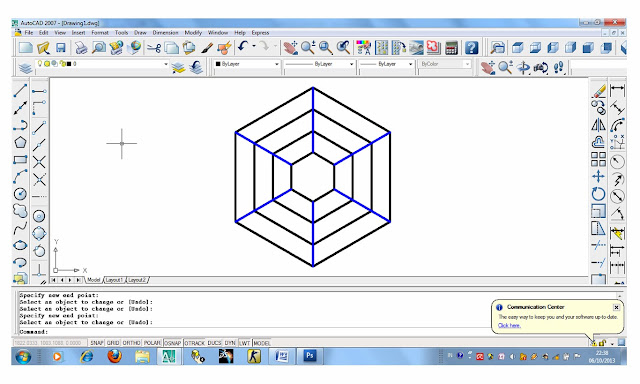
Images , irregular octagon before the command was given to AUTO CAD LENGTHEN

4 . Drag endpoint to endpoint selection and specify the new


Images , irregular octagon after the command was given to AUTO CAD LENGTHEN


Command window text editor on AUTO CAD

Automatic save to C : \ Users \ MYNOTE ~ 1 \ AppData \ Local \ Temp \ Drawing1_1_1_6500.sv $ ...
Command : LENGTHEN
Select an object or [ DELTA / Percent / Total / Dynamic ] : DY
Select an object to change or [ Undo ] :
Specify new end point :
Select an object to change or [ Undo ] :
Specify new end point :
Select an object to change or [ Undo ] :
Specify new end point :
Select an object to change or [ Undo ] :
Specify new end point :
Select an object to change or [ Undo ] :
Specify new end point :
Select an object to change or [ Undo ] :
Specify new end point :

auto cad 2007


In the present era , the development of technology was very
fast . Almost all aspects of life began to be touched with
the name of technology . With all the technology feels more
easy to do . Various innovations do not stop
to increase the use and application of technology in
human life . One of the rapidly evolving technology
is CADD ( Computer Aided Design and Drafting ) . development
This technology aims to make it easier for designers
and drafter to visualize their ideas into form
image .
AutoCAD is a CAD program that is quite well known
by the designer and drafter because it offers a variety of
ease and excellence . AutoCAD shown to facilitate
the work of the designer and drafter in visualizing
ideas and their ideas . AutoCAD created or issued
by Autodesk Corporation in 1982 . Starting from the first
coined until the latest products launched ,
AutoCAD continues to experience growth and able to take
to the development of current CAD technology .
AutoCAD is an application program that is used to
drawing and design , such as for modeling ,
create architectural drawings , machinery , civil, electrical , manufacturing , and
others. With AutoCAD , the design process becomes easier ,
fast , and accurate . AutoCAD has excellent facilities
complete . A design can be created with AutoCAD
with easy to edit when there are mistakes and shortcomings ,
has a very varied picture layout , scale
can be changed , adjusted to the paper size , and so
practical storage.
1
B. Overview CADD
Computer Aided Design and Drafting or better known as
CADD , has been there since 1964 but their use is still
limited to the mainframe . In 1982 , the system began to be known
CADD on a PC with a software that has
AutoCAD name . Now we have to know AutoCAD software
to release 2007 with great capabilities and benefits
and awesome that no longer forms a 2D image
or 3D that can not be drawn by the program .
In AutoCAD there is also a programming language called
AutoLISP that allows us to develop their own
AutoCAD software and can be used as a program
specific , tailored to our needs and requirements .
CADD operator communicates with the computer through input
devices , such as keyboard , mouse , digitizer . In addition , other input
can come from a scanner or file with another extension
such as 3DS , DXF , DXB .
CADD software that will be discussed are AutoCAD , where
The software has great flexibility . AutoCAD
not only be used for specific applications , such as architecture ,
mechanical , geodesy , or machines , but has the ability
to draw anything . If we want to make AutoCAD
a dedicated software , we can add that
called " 3rd party software " , for example :
• Autodesk Architectural Desktop for architectural applications .
• AutoYatch to design boats and sailing boat ( yacht ) .
• Auto - Site - Lite lighting calculations for applications .
• Autodesk Land Desktop for civilian applications , mapping , and
urban design .
• AutoCAD -MAP for GIS applications .
• SEW - CAD for fashion and textile applications .
• Autodesk Mechanical Desktop for mechanical applications .
With the software mentioned above , we can more
increase productivity in areas of our work .

Sunday, November 3, 2013

DRAWING TECHNIQUES AND RELATED GRAPHICS DESIGN by BUDI MARYANTO,ST


Engineering graphics and design are interrelated in the overall design process , then the people who manage the design lay out , the detailer , and production engineers , each time having to work closely with the project leader of the group , as a part of the overall team work . In general , all the people who are assigned to a project , both expert designers and those who occupy businesses in every stage of the design should really master the technique chart . A design engineer , in order to succeed as a design specialist should undergo training in this field . At the very least , should be able to manage freehand sketch with good results and have the knowledge to work on all forms of graphic expression that has been in the present


Picture machine in the production process

People - people from supporting the design may be expected to be able to solve some of the questions arising in graphic design , layout design and manage models , and finally , managing the design and structure needed to be used in a production workshop that they all should have some basic education school and then gained additional experience in which they work in order to become familiar with the standard practices of the company

Friday, November 1, 2013