Wednesday, October 30, 2013

Dimensional Management


Our approach to Dimensional Management is simple – to teach you and your staff to recognize and eliminate dimensioning and tolerancing problems before they happen. This is done through education, careful coordination between design, manufacturing, inspection and assembly, coordination with suppliers, properly applying GD&T, and by using Tolerance Analysis techniques to ensure top level assembly requirements are achieved.
It is also critical that the design approach leads to realistic tolerancing requirements. We strive to ensure that component tolerances are manufacturable and inspectable using the methods available. Our goal is to help you optimize your Dimensioning and Tolerancing schemes and to help you improve your bottom line.


We teach you how to coordinate your Design and Tolerance Analysis efforts with your Manufacturing, Inspection, Quality and Assembly efforts. The entire process is considered and coordinated, leading to less problems down the line.
Dimensional Management is the key to increasing your productivity, optimizing your processes, reducing your cycle time and increasing your quality. We have helped many companies to become more successful by improving their product definition and optimizing their tolerancing practices.
Although our Dimensional Management Courses may be taught stand-alone, they are most effective when taught in conjunction with Tolerance Analysis and GD&T Courses, as all three are interrelated. Proper application of GD&T is necessary to be able to define allowable part variation, and for Tolerance Stackups to be accurate parts and assemblies must be defined using GD&T.
Our Dimensional Management Courses are available in our standard format or they may be customized to your products and processes.


LETTERS AND NUMBERS ON AUTO CAD


Each image technique requires letters , numbers and symbols that are used to give the size , the record , and the title of the picture . Characteristics that need to be in letters and numbers in the image techniques are : clear , fast , easy , uniform , economical and simple .
The form of letters and numbers that is often used is a form of writing ISO . ISO letter is often used because it is not too much variation in the form of letters . Auto CAD as one who has basic computer program to draw ISO teknik.Huruf there are two types-
• Vertical type
• Type tilted at an angle of 15 degrees
The most commonly used type is verikal . Use gothic letters to write numbers and letters on the drawing techniques performed manually using letters mall . Posting letters and numbers written on paper directly image requires special skills and should follow the rules in force in accordance with the standards ( ISO 3098/I- 1974)

At AUTO CAD to write letters and numbers by typing the command to make Dtext as letters and numbers , for editing the letters and numbers menggetikan Ddedit


examples of writing provisions iso


Command : dtext

Current text style : " Standard " Text height: 2.5000
Specify start point of text or [ Justify / Style ] :
Specify height < 2.5000 > : 7.5

Specify rotation angle of text < 0 > :

Tuesday, October 22, 2013

GAZEBO By Budi Maryanto , ST


Our thanks to the AUTO DESK who have developed the software engineering AUTO CAD and 3 DS MAX , so I can get an idea to draw a gazebo that is used for dining at food stalls .


GAZEBO design drawings

Gazebo used to draw ideas for the dining room on the Javanese food stalls inspired by the time my Big Family Meeting held at Blue Tent Restaurant in Sukoharjo region . However regrettable that the layout of the restaurant is at the heart of making it less feels good atmosphere .
I think if it 's in the middle of rice fields impression of making the gazebo will be more pronounced , because the history of the gazebo is started from the hut of the peasant . Wherein , the farmers usually will make the hut in the middle of rice fields as a place to rest and to eat and drink after a tired hoe .
This idea then pour in pictures gazebo , equipped with tables and chairs as a place to eat and drink .

Monday, October 21, 2013

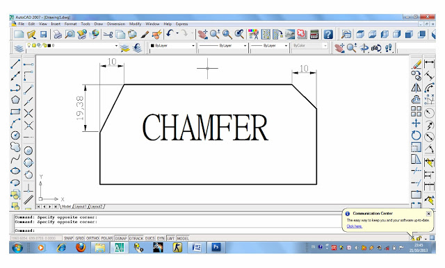
Chamfer ORDERS ON AUTO CAD , BY MIND Maryanto , ST


Chamfer is one of AUTO CAD commands into the Modify group . Chamfer command is used to create a line between two lines are not parallel . In general, the command to create a chamfer bevel on the top edge of a corner . Chamfer command can be used to make a bracket for all angles polyline

To be able to use the chamfer command in AUTO CAD , follow the steps below.
1 . Prepare the image to be in chamfer


Picture before in chamfer

2 . Use one of the following commands to call chamfer
a. On the Modify menu , select the chamfer
b . At the command line type the chamfer or type cha which is a short-cut chamfer enter the command

3 . At the command line type D or Distance
On the command line in the command line
 ( TRIM mode ) Current chamfer Dist1 = 0.0000 , = 0.0000 Dist2
  Select first line or [ Undo / Polyline / Distance / Angle / Trim / Method / Multiple ] : D

4 . The first of the size of the input value that will be created on the hypotenuse which is 10
On the command line in the command line
Specify first chamfer distance < 0.0000 > : 10

5 . The first of the size of the input value that will be created on the hypotenuse that is 20
 On the command line in the command line
Specify second chamfer distance < 10.0000 > : 20

6.  Click on the first line and click on the second line and then press enter or right click on the mouse

How to get to use the chamfer angle :
1 . Use one of the following commands to call chamfer
a. On the Modify menu , select the chamfer
b . At the command line type the chamfer or type cha which is a short-cut chamfer enter the command

2 . At the command line type A or ANGLE
On the command line in the command line
  ( TRIM mode ) Current chamfer Dist1 = 10.0000 , Dist2 = 20.0000
  Select first line or [ Undo / Polyline / Distance / Angle / Trim / Method / Multiple ] : A

3 . Put value on the size of one of the lines that will be in chamfer
On the command line in the command line
Specify chamfer length on the first line < 0.0000 > : 10

4 . Input angle values ​​that will be used to make the angle of the chamfer
On the command line in the command line
Specify chamfer angle from the first line < 0 > : 45

5 . Click on the first line and click on the second line and then press enter or right click on the mouse


Image after the chamfer

Friday, October 18, 2013

FILLET


In AUTO CAD fillet is one of the commands that go into modify groups .
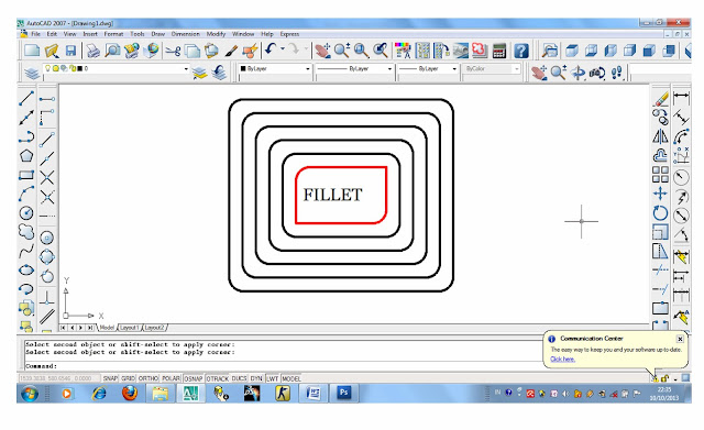
Fillet in AUTO CAD command serves to connect two objects or lines using circular arc with a radius the size specified .
How to use fillet to connect two lines with a circular arc using the radius of the large size specified
1 . Type the fillet in the command window
2 . On the form in the command window exit command
Current settings: Mode = TRIM , Radius = 0.0000
Select first object or [ Undo / Polyline / Radius / Trim / Multiple ] : type R
3 . On the form in the command window exit command
Specify fillet radius < 0.0000 > : type the number that represents the size of the specified radius . In this case we give the size of the radius of 90
4 . Click on the first line and second line then press enter , or right-click


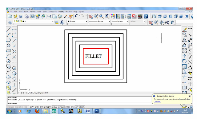
Picture before in fillet


Images after in fillet

Command : fillet
Current settings: Mode = TRIM , Radius = 0.0000
Select first object or [ Undo / Polyline / Radius / Trim / Multiple ] : r
Specify fillet radius < 0.0000 > : 90


Drawing design table by Dian Pramesti,S.Pd


Drawing design table

Thursday, October 10, 2013

picture Hammer By Budi Maryanto, st


Working drawings Hammer


picture Hammer

ORDER FOR CUT TRIM LINE OBJECT OR OBJECTS BY MIND Maryanto , ST


Command trim function in AUTO CAD is to cut the line or drawing object , so that a line or object images may be cropped right on the edge of the boundary depicted by lines or other drawing objects . Using TRIM cutting can be done on , line , arc , circle , polyline , elippse , spline , xline , region , block and can also be done in the form of spatial objects in the paper space viewport 
.
HOW TO USE THE ORDER OF THE TRIM ON OBJECT IMAGES
The steps are as follows
1 . Prepare an image object as below


Image ; object image will be cut with the TRIM command

2 . Perform one of the following commands , to call the TRIM command
a. Click the Modify icon on the tool bar TRIM
b . On the MENU BAR click Modify , and select and click TRIM
c . In the command window , type the TRIM then enter or right click on the mouse
3 . Select and click on the line that acts as a cutter , in this case is the line that had me give a red color and then press enter or right click on the mouse


Image ; object image that acts as a cutter in this case the lines are colored red

4 . Select and click on the line will be cut by using the TRIM command , in this case the black line , then press enter or right click on the mouse . Then the line is selected and clicked to cut and does not appear on the monitor screen , while the connection of a line that is not selected and not clicked on is not truncated


Image ; object image will be cut by using the TRIM command , it lines the black